
Installation method for a parking lot system ground sensor coil (complete construction process)
I. Preparation before construction
a. Site survey
-
Avoid cracks and areas with dense steel bars and metal manhole covers. There should be no cable of 220 V or above within 1 m around the coil.
-
The center distance between adjacent coils should be at least 2 m; if the detector is shared, it can be reduced to 0.5 m, but the frequencies must be staggered.
b. Materials and tools
-
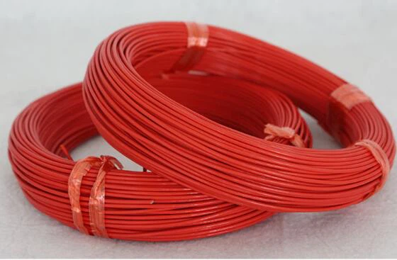
Wire: 1.0 mm2 high-temperature-resistant tinned copper wire or Teflon multi-strand soft wire, rated from -40 C to +125 C.
-
Sealing: asphalt, epoxy resin or soft polyurethane, with a Shore hardness of at least 60 after curing.
-
Tools: road cutter (blade 4-8 mm), inductance tester, LCR meter, angle grinder, wire crimping pliers, and so on.
2. Wire trough cutting
a. Shape and size
-
A rectangle is the most common shape: the long side runs perpendicular to the driving direction, with a length-to-width ratio of 1.5:1 to 2:1.
-
Typical size: 2 m (length) x 1 m (width) for a 3 m wide lane; 45-degree chamfers are made at the four corners to prevent cutting and shedding.
-
Groove depth 30-50 mm, width 4-8 mm, error within plus or minus 2 mm; at the same time, cut a feeder groove to the gate chassis.
b. Groove cleaning
- Rinse out the mud with a high-pressure water gun, dry the groove with a hair dryer until the bottom turns white, then apply primer to enhance bonding.
3. Coil winding
a. Number of turns and inductance
-
Target inductance 100-300 uH; a 2 m x 1 m coil can reach 180 uH with about 6 turns.
-
Measure while winding: use an inductance meter to calibrate in real time. The smaller the circumference, the more turns are needed.
b. Winding specifications
-
The wires should be straightened, close to the bottom, without crossing, and each layer tightly attached; the "6+2" principle is recommended: 6 layers for the base and 2 more layers depending on the test results.
-
There must be no joints inside the coil; if a connection is unavoidable, it must be welded and covered with heat-shrink tubing for double waterproofing.
4. Lead processing
a. Twisted pair shielding
-
The output line should be no longer than 5 m, with at least 20 twists per meter; the end uses shielded twisted pair (STP), and the shielding layer is grounded at one end.
-
The lead is passed through a PVC tube or metal tube, and the distance from strong current should be at least 30 cm; add a metal tube shield when it is impossible to stay far away.
b. Reserved length
- Reserve 1.5-2 m to the vehicle detection end for easy wiring and maintenance.
5. Sealing and curing
a. Layered potting
- First fill a 10 mm fine-sand buffer, then pot with molten asphalt at 160-180 C or two-component epoxy resin, and cure for 24 h.
b. Surface repair
- The height difference between the sealing surface and the road surface should be no more than 2 mm. After grinding with an angle grinder, apply reflective paint to restore the appearance of the road surface.
6. Debugging and acceptance
a. Single machine test
- No-load inductance 100-300 uH; completely cover the coil with a 300 mm x 300 mm x 2 mm iron plate, the indicator light changes from flashing to constant light and then returns after the plate is removed, and the gate drops automatically within 3 s for the test to pass.
b. System joint debugging
-
Vehicles pass at 5 km/h, trigger delay no more than 50 ms, false alarm rate below 0.1%.
-
Linked with license plate recognition and the gate: the response of pressing the wire and lifting the pole is less than 1.5 s; in the anti-smash test, the pole stops and rebounds within 0.3 s when it encounters a metal signal while falling.
7. Common problems and countermeasures
-
Low inductance: add 1-2 turns to compensate for the influence of underground steel bars.
-
Crosstalk between adjacent coils: the difference in the number of turns should be at least 2 turns, and the difference in operating frequency should be more than 5 kHz.
-
Winter cracking: use low-temperature flexible epoxy resin or add a nylon rope to enhance toughness.
By following the steps above, the ground sensor coil can be ensured to operate stably for a long time and to provide reliable trigger signals for parking lot gates, license plate recognition and other systems.